

FITTING A REMOVABLE BARTON TRAVELLER SYSTEM
Part #s 20 910 & 24 910
IMPORTANT:
READ THESE INSTRUCTIONS BEFORE COMMENCING FITTING YOUR NEW BARTON BALL BEARING MAINSHEET SYSTEM.
- Do not remove the traveller car from the beam track unless using the loading track provided. Removal of the car will result in ball bearings coming loose from bearing galleries and create difficulties in re-assembly.
- To load traveller, butt the end of the loading track to the end of the beam track and carefully run traveller car across. (see separate sheet)
- Make a careful inspection of the mounting area for the traveller end plates (part #s 20 090 & 24 090, if sold separately). Typically this will be the cockpit vertical sides. You will need access to the inside of the cockpit vertical side to fit a backing plate made of wood or aluminium (not provided) which needs to be both substantial and wide enough to spread the vertical load. Minimum dimensions 250mm x 250mm and bonded into place.
- Some cockpit sides are not vertical so a spacer will need to be fabricated to ensure vertical plates are exactly vertical against the cockpit sides. Either hardwood or nylon block can be used as these can be machined to fit.
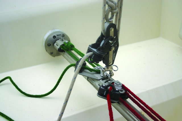
- The complete kit (20 910 & 24 910) comes with one end fitting pre-drilled and tapped in the correct position with fixing bolt to allow correct spacing from the end plate. This distance needs to be mirrored at the other end once the beam track has been cut. (see section 5)
Fastening sizes for end fittings are as follows (not provided):
Size 1 Traveller Systems 5mm Size 2 Traveller Systems 6mm
Ensure that the spacer provided is used inside the end fitting extrusion to prevent crushing when tightening the fastening bolt.
- With the traveller end plates fixed in place on the cockpit sides, carefully measure the distance between the internal face of the end plates each side. The maximum float of the beam track is 4mm so cut the beam track exactly at right angles taking this into account.
- To fit the remaining end fitting, position as in section 4. Drill and tap the track to accept end fitting fastening taking note of section 5. Use Duralac or other barrier paste to prevent dissimilar metal corrosion between fixing bolt and aluminium track.
- The maximum un-supported span for beam track is as follows:
Size 1 – 400mm for yachts up to 8.50m (28ft)
Size 2 – 700mm for yachts up to 11.0m (36ft)
Size 2 – 900mm for yachts up to 9.75m (32ft)
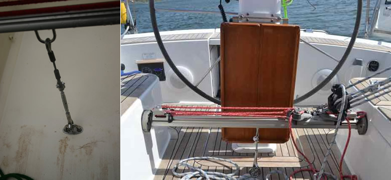
Un-supported span wider than above will require fitment of a removable pelican hook fitted to a barrel adjuster and short wire strop. This is fitted to a pad eye in the cockpit floor and a ‘u’ bracket fitted into the slot on the underside of the beam track.
If in doubt about specification please contact Barton Marine Ltd for guidance.